Home
About
Team Members
Project Description
Our Strategy
Bill of Materials
Gems of Wisdom
Software
Pin Layout
State Charts
>
Master State Machine
Game State Machine
JSR
Joust State Chart
Round2Drive State Chart
Recess2 State Chart
Round3Drive State Chart
SimpleDriveToA State Chart
SimpleDriveToB State Chart
Pseudo Code
>
MasterSM
GameSM
JoustSM
SimpleDriveToASM
SimpleDriveToBSM
Round2DriveSM
Round3DriveSM
Recess2SM
JSR
Code Listing
>
MasterSM
GameSM
Round State Machines
>
JoustSM
SimpleDriveToASM
SimpleDriveToBSM
Round2DriveSM
Recess2SM
Round3DriveSM
JSR Service
Event Checkers
Component Controls
>
Digital Control
Drive Motors
Launcher Control
Reload Control
Servo Control
Ultrasonic Control
Headers
>
ES_Configure
Pins
Commands
Drive
Electrical Design
Mechanical Design
Jousting
Electrical Design
Mechanical Design
Shooting
Electrical Design
Mechanical Design
Other Stuff
Robot Drawings and Dimensions
Power
JSR
Pin Layout
The following diagram describes how the pins on the E128 are distributed among the different subsystems:
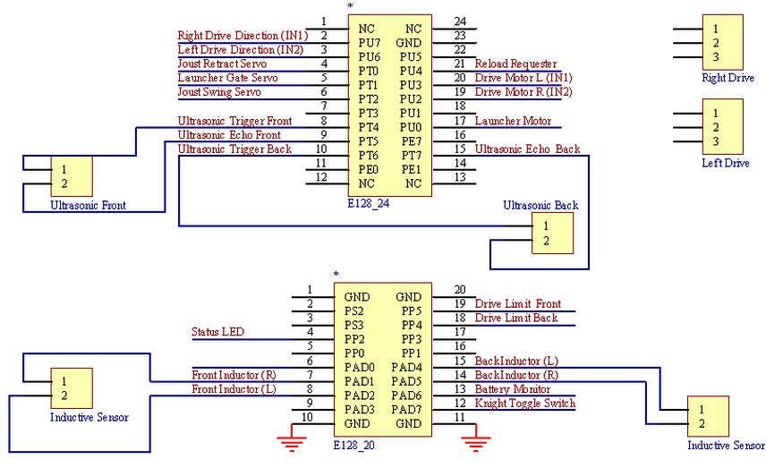
Digital:
Drive Direction
Knight Toggle Switch
Limit Switches
PWM:
Motors
Reload Circuit
Timer:
Ultrasonic Sensor
Servos
Analog:
Inductive Sensing
Voltage Sensing